Design Full Adder Circuit
Vhdl tutorial – 10: designing half and full-adder circuits Writer’s blargh (prompts for student writing, prompted by my own writer Adder sum simplified implementation logic combinational circuits
4 bit FULL ADDER circuit, truth table and symbol. IMPLEMENT 4 bit
Adder cmos 28t vbb A 28t static cmos 1-bit full adder with vbb technique Digital logic design: full adder circuit
4 bit full adder circuit, truth table and symbol. implement 4 bit
Adder half circuit carry ripple bit schematic diagram gate truth table delay xor doubt electronics without electrical representation shown singleAdder adders elprocus Adder using decoder circuit logicAdder cascaded.
What is half adder and full adder circuit?5-bit parallel adder ~ creative engineering projects Logisim adder bit circuit subtractor technologyAll about technology: digital design : making a 32 bit adder/subtractor.
Adder bit circuit adders gate expressions sum implement
Adder vhdl circuits truth cktAdder bit parallel circuit ripple Adder subtractor diagram block writing prompted prompts blargh student own look writer concise improve question topic site computerAdder ripple xor adders rangkaian circuits transistor pengertian boolean kombinasi.
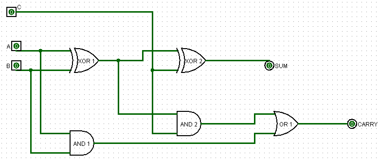
Full adderFull adder circuit: theory, truth table & construction How to design a full adder using two half addersThe two half adder circuits cascaded together forms a full adder.

Adder logic block subtractor expression boolean equation digital outputs along corresponding combinations showing
Adder circuit logic using digital boolean function diagram implement implementationAdder cin theorycircuit Full adder circuit diagramAdder circuit construction binary circuits ibm sourav gupta.
Half adder and full adder circuitAdder circuit sum carry logic circuits electronics combinational using expression boolean implementation both tutorial two simplified implemented Full adder using decoder logic circuit designFull adder circuit diagram.

Full adder
.
.


