Full Adder Circuit Diagram Using Nand
Design full adder using 3:8 decoder with active low outputs and nand gates. Adder subtractor diagram block writing prompted prompts blargh student own look writer concise improve question topic site computer Patent us8405421
Full 1 Bit Adder using NAND - CircuitLab
Adder half truth input outputs combinations corresponding possible Half adder and full adder circuit Edacafe: power, accuracy and noise aspects in cmos mixed-signal
Adder cmos circuit diagram fa transistor using 28t transistors implementation edacafe transmission gate power fig www10 phdthesis book
Adder nand multisimPatents claims Decoder adder using nand gates implement circuit active low outputs logical comment add linkFull 1 bit adder using nand.
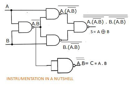
Instrumentation in a nutshell: implementation of half adder with nand gatesAdder nand implementation instrumentation nutshell Adder schematic circuitWriter’s blargh (prompts for student writing, prompted by my own writer.

Full adder (nand)
Adder bit nand using circuit circuitlab description .
.


