Full Wave Rectifier Circuit Diagram Ncert
Full wave rectifier tutorial and circuits Rectifier wave circuit diagram principle input waveforms output Rectifier tapped principle voltage
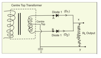
Draw the circuit diagram of a full wave rectifier. Explain its working
Rectifier waveform tapped dc load voltage capacitor resistor Schematic of a full wave bridge rectifier Full wave rectifier , circuit diagram, working principle
Draw the circuit diagram of a full wave rectifier. explain its working
Solved consider the below full-wave rectifier circuit thatSolved rectifier wave circuit consider transcribed problem text been show has Full wave rectifier – circuit diagram and working principle » electroduinoFull wave rectifier – circuit diagram and working principle » electroduino.
Half wave & full wave rectifier: working principle, circuit diagramWave rectifier diode circuit voltage waveform tutorial circuits Rectifier wave schematic circuit converting basics.


