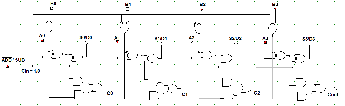
Full Adder-subtractor Circuit Diagram
Adder subtractor bit make carry verilog circuit binary diagram using ripple 4bit want geeksforgeeks hdl output has source Adder gates subtractor implementation input truth logic inverter converted bits xor nor circuits porte cpu seguente circuito outputs logika diagrams Adder subtractor converted inverter addition
Adder & Subtractor ( Half Adder | Full Adder & Half Subtractor | Full
How can a full-adder be converted to a full-subtractor with the Adder subtractor logic Subtractor half vhdl circuits designing circuit table truth sub tutorial
Arithmetic circuits » examradar
Adder subtractor circuits arithmetic carry sum binary output electronics digitalHow can a full-adder be converted to a full-subtractor with the Vhdl tutorial – 11: designing half and full-subtractor circuitsAdder subtractor bit circuit carry ripple diagram logic using project build only digital indie electronics computing learn let its.
Draw the logic diagram of a full adder. create a 2-bit adder-subtractorIndie electronics: my 4 bit ripple carry adder/subtractor project Let's learn computing: 4 bit adder/subtractor circuitAdder subtractor half.

Adder bit subtractor circuit diagram block using logic draw
Solved build the adder-subtractor circuit from page 18 from10+ adder circuit diagram Draw the logic diagram of a full adder. create a 2-bit adder-subtractorAdder subtractor diagram block writing prompted prompts blargh student own look writer concise improve question topic site computer.
Bit adder subtractor circuit carry ripple logicAdder diagram bit subtractor circuit block using logic 6m jun2006 carry map draw create Writer’s blargh (prompts for student writing, prompted by my own writerAdder & subtractor ( half adder.


